WebIO Internet enabled Relay and Input board
The Relay and Input board is an optional add-on for WebIO version 3.6 or greater.
Using the WebIO Internet/web interface you can control the hardwire contacts of the 4 SPDT relays of the add-on relay board
and be notifide of input state changes and perform control automation.
This relay board can be used to control hardwired devices such as pumps, alarms, electronic door locks/strikes, etc,
with the reliability of hard wiring and without using or relying on a complex automation protocol.
Each Relay has connections "A" and "B" where "A" is a normally closed connection and "B" is normally open.
Using the WebIO "Exp" webpage you can set the state of each relay to "A" or "B".
The Relay board also has 4 optically isolated inputs which can be used to monitor things such as a hardwired security systems entry sensors, hardwired motion
sensors, house doorbell or anything else that can provide a closed contact or 3Vdc power.
When an input changes states (high/low) the relay board notifies WebIO.
WebIO internal automation can be configured for each input such that when an input changes states
an X10 powerline command can be sent.
Each input can be assigned an X10 house and unit code such that when an input goes "high" an X10 "on" message
is sent for the defined house/unitcode. When input goes low an X10 "off" message is sent.
WebIO also sends each input state change over the TCP/IP network where the WebIO-TM software running on a computer
can then process the WebIO message to perform additional and more complex automation
and send event notifications as email or text message based on the state of the input.
The inputs require 3.5VDC to transition to a "high" state, when power is removed the input state goes "low".
The relay board provides LED indicators for each relay and input to signify state.
|
Relay board features:
-
Easy to install, just plug into WebIO expansion port and DC powersupply.
Connecting your own equipment to control or monitor can be from easy to complex.
-
Embedded device reliablilty, doesnt require X10 or any other automation powerline or wireless protocol.
-
Provides four SPDT relays. Relay contacts rated: 15A at 120VAC, 15A at 24VDC, 10A 250VAC.
When controlling AC powered devices its recommended to use the relay board to control yet another high
current relay. This helps ensures AC power seperation from the DC powered relay board.
-
Provides four optically isolated inputs. Inputs require 3DVC to transition to a "high" state.
-
The WebIO embedded web server provides web page interfaces for changing relay states and
monitor of inputs, via remote Internet access
via PC computer or cell phone/Smartphone web browser.
-
WebIO internal automation for each input. For example, an input can be configured such that when
it goes to a "high" state from a connected doorbell being pressed, WebIO internal automation will then ring an X10 chime, no PC computer required.
-
When used with WebIO-TM software running on a PC on the same local network or accross the Internet,
Input state changes are sent from WebIO to the WebIO-TM software for additional processing, X10
automation, email and text message notification.
|
|
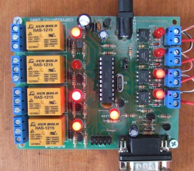
Relay and Input board. Notice the LED indicators for each relay and Input.
|
|
| WebIO Expansion Port |
The WebIO Expansion Port for Relay Board
The image to the right displays the WebIO connection panel for WebIO version 3.
WebIO version 2 does not have an expansion port.
From left to right:
-
Power connector, accepts 9-12 volts DC center pin positive (Center Pin Positive is very important)
on a typical 5.5mm O.D. x 2.1mm I.D. (Inside Diameter) barrel connector.
-
WebIO Lock-Program Switch. Configuring WebIO user settings requires switch to be in the "Prg" position.
Rebooting WebIO with the switch in the "Prg" position causes restoration to factory default settings.
Remember to switch back to "Lock" position when finished with configuration changes.
-
The Expansion Port via RJ12 connector. This is the connection for the Relay Board.
-
X10 transceiver connection via RJ12 connector. Connect to TW523 compatible X10 Transceiver
or X10 Firecracker wireless X10 transmitter (requires special cable).
-
Ethernet Connection via RJ45.
|
|
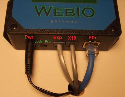
The image above displays the WebIO connection panel.
|
|
| WebIO Expansion Port Webpage |
WebIO web page for expansion port
The image to the right displays the WebIO internal webpage for the exansion port interface.
This web page is used to directly control and monitor the Relay and Input add-on board.
This expansion port interface is new to WebIO version 3.6.
To change the state of a Relay, select the relay to change (relay 1-4) in the "Cmd" command field
drop down box. Next select the Relay state of "A" or "B".
Each Relay has connections "A" and "B" where "A" is a normally closed connection and "B" is normally open.
When a selecting state "B", the relay is energized and contact "B" is closed and the LED indicator for the
relay lights.
If a passcode is configured for WebIO, then the passcode is required each time you send an expansion port command.
Selecting the "Execute" button should immediatly change the relay state.
Below the "Execute" button is an indication of the relay states and input states.
For example: "Relays: BBAB" indicates that relay 1, 2 and 4 are in state "B" and relay 3 is in state "A".
"Inputs: HHLL" indicated that input 1 and 2 are in "high" state and inputs 3 and 4 are in "low" state.
After changing a relay state, wait 1 second then select the "refesh" link to refresh the relay and input states.
To only request update of relay and input states, select command "Refresh States" from the drop down list.
Each relay and input can be assigned a short 8 character name.
The names are listed on the "Exp" web page for reference. The names are assigned using the WebIO-TM PC app.
Each relay board input can be assigned an X10 automation House code and Unit code.
The House and Unit code assinged to the input is displayed after the input name.
The WebIO-TM PC app is used to configure the Input Automation settings,
afterwich the PC app is no longer required for WebIO to perform the Input Automations.
Additional and more complex automations can be defined and performed using the WebIO-TM software
along with Input Event email and SMS/Text notifications.
|
|
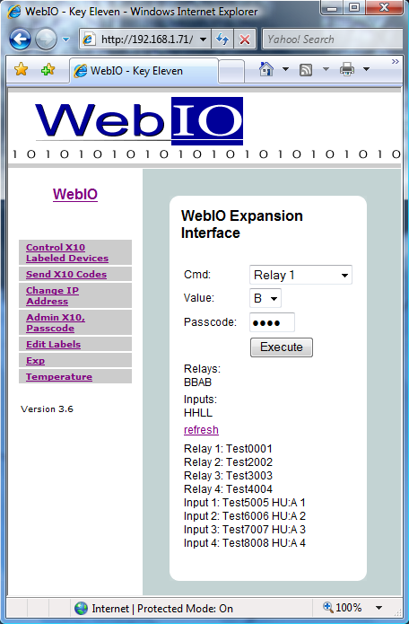
The image above displays the WebIO internal web page for the Expansion port.
|
|
|
|